ER Diagram: Entity Relationship Diagram Model | DBMS Example
Entity Relationship Diagram, or ERD for short, is a type of diagram that illustrates the connection between different entity sets that are kept in a database. ER Diagram is an abbreviation for “Entity Relationship Diagram.” In a nutshell, ER diagrams are useful tools for clarifying the logical organisation of database tables. Entities, attributes, and relationships are the three fundamental building blocks that are used to construct ER diagrams.
ER Diagrams are comprised of various symbols, the most common of which are rectangles, ovals, and diamonds. Rectangles are used to represent entities, ovals to define attributes, and diamonds to represent relationships.
An ER diagram and a flowchart, at first glance, appear to be very similar to one another. However, the ER Diagram is a one-of-a-kind model because it utilises a wide variety of specialised symbols, each of which has a specific meaning. ER Diagrams are used to represent the entity framework infrastructure, which is their primary purpose.
What is ER Model?
Entity Relationship Model, also known as ER Model, is a conceptual data model diagram that operates at a high level. A well-designed database can be created with the assistance of an ER model by methodically analysing the data requirements. The ER Model depicts the entities that exist in the real world as well as the connections that exist between them. Before beginning to implement your database, it is recommended that you first create an ER Model using DBMS. This is a best practise.
You can produce a database that is well designed with the help of ER Modeling, which assists you in methodically analysing the data requirements. Therefore, finishing your ER modelling before implementing your database is something that is recommended as a best practise.
History of ER models
The ER model can be represented visually using tools known as ER diagrams. These diagrams are helpful. In 1971, Peter Chen came up with the idea for an ER Diagram in an effort to standardise a convention that could be applied to relational databases as well as networks. He intended to take a conceptual modelling approach in the form of an ER model.
Why use ER Diagrams?
The following are some of the most important justifications for using the ER Diagram:
It assists in the definition of terms associated with entity relationship modelling.
Give a rundown of how all of your tables are supposed to connect to one another and what fields are going to be on each table.
Contributes to the characterization of entities, attributes, and relationships
ER diagrams can easily be converted into relational table formats, which makes it possible to rapidly construct databases.
Database designers are able to utilise ER diagrams as a blueprint for the implementation of data in various software applications by using these diagrams.
With the assistance of the ERP diagram, the designer of the database is able to improve their comprehension of the data that is going to be included in the database.
Users can be informed of the logical structure of the database through the use of ERD Diagram, which enables you to communicate with them.
Information Regarding the ER Model Diagram
Now, let’s take a look at some interesting information regarding the ER Diagram Model here in this tutorial on the ERD Diagram.
ER Diagrams Symbols & Notations
You are able to create a Database Design using the ER model.
It is a graphical tool that is simple to use and is widely utilised in the process of database design.
It is a graphical user interface representation of a database’s logical structure.
It assists in the identification of the entities that are present in a system as well as the connections that exist between those entities.
ER Diagrams The Use of Symbols and Notations
Diagram of Relationships Between Entities The rectangle, oval, and diamond are the three primary symbols that make up Symbols and Notations. These symbols are used to represent the various relationships that exist between elements, entities, and attributes. Within the ERD Diagram, there are a few sub-elements that are founded on the principal elements. An Entity Relationship Diagram, or ER Diagram, is a graphical representation of data that, by employing a variety of ERD Symbols and Notations, explains how the data are related to one another.
The following is a list of the primary components and their corresponding symbols found in ER Diagrams:
ER Diagrams Symbols & Notations
Rectangles: Entity types are represented by this symbol on the Entity Relationship Diagram.
Ellipses: Symbols are used to represent qualities.
Diamonds: This icon depicts the various forms of relationships.
Lines: It does so by linking attributes to entity types as well as entity types with various relationship types.
The attributes are highlighted because they are the primary key.
Double Ellipses: Represent multi-valued attributes
ER Diagram Symbols
ER Diagram Symbols
Structure of the ER Diagram’s Components
This model is founded upon the following three fundamental ideas:
Examples of an ER Diagram Containing Entities, Attributes, and Relationships
For illustration’s sake, let’s say that a database for a university contains separate entities for Students, Courses, and Lecturers. Some of the attributes that can be associated with the Students entity are Rollno, Name, and DeptID. It’s possible that they have relationships with the Courses and the Lecturers.
Structure of the ER Diagram’s Components
Structure of the ER Diagram’s Components
Components of the ER Diagram
a thing that exists in the real world and can be either living or nonliving, as well as easily recognised and unrecognisable. Our database will contain information about anything that is relevant to the operation of the business. It could be a tangible item, a simple fact regarding the company, or an event that takes place in the real world.
A place, a person, an object, an event, or even a concept can all serve as examples of entities that store data in a database. Entities are defined by the fact that they always have both a unique key and at least one attribute. Every ‘entity’ is composed of a set of ‘attributes’ that act as a representation of that entity.
These are some examples of entities:
Employee, Student, or Patient: the Individual
Location: Shop, or a Building
Car, product, and machine are the objects in question here.
Event: Sale, Registration, Renewal
The Concepts of an Account and a Course
Symbolic Representation of an Entity
Identified entity: a student
A collection of entities of the same kind is known as an entity set. There is a possibility that it will contain entities whose attributes share similar values. Properties, which are also referred to as attributes, are what entities use to represent themselves. Every attribute has a value that is unique to itself. An example of some attributes that could be associated with an entity is a name, age, and class.
WHAT IS ENTITY?
There could be various departments at a university. All of these departments employ a wide variety of lecturers and make available a range of courses.
Each programme consists of a certain number of classes. Students begin by signing up for a specific programme and then enrolling in a variety of classes. Each class is led by a lecturer from the respective department, and each lecturer is responsible for a unique set of students.
Relationship
A connection between two or more entities is all that is required to define a relationship. As an illustration, Tom is employed in the Chemistry department.
Relationships involve the participation of entities. Verbs and verb phrases allow us to frequently determine the nature of relationships.
Take, for instance:
You are currently present at this lecture.
I will now proceed with the lecture.
Relationships, much like entities, can be categorised according to the types of relationships they have:
A student is seen in the audience of a lecture.
A lecture is currently being delivered by a lecturer.
Weak Entities
A weak entity is a type of entity which doesn’t have its key attribute. It can be identified uniquely by considering the primary key of another entity. For that, weak entity sets need to have participation.
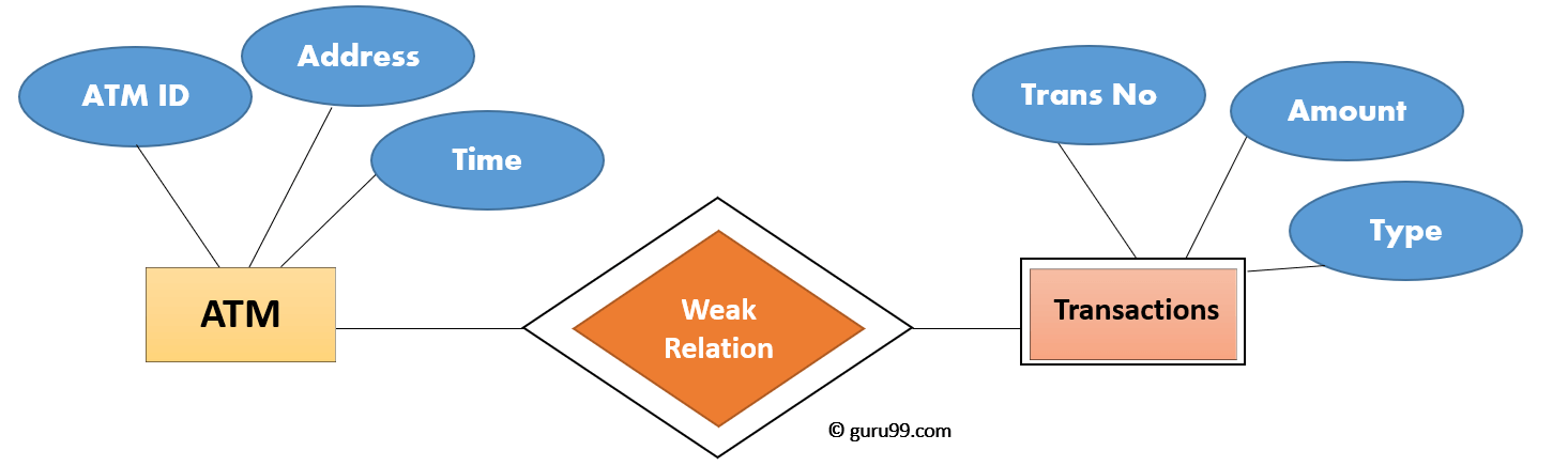
In above ER Diagram examples, “Trans No” is a discriminator within a group of transactions in an ATM.
Let’s learn more about a weak entity by comparing it with a Strong Entity
| Strong Entity Set | Weak Entity Set |
|---|---|
| Strong entity set always has a primary key. | It does not have enough attributes to build a primary key. |
| It is represented by a rectangle symbol. | It is represented by a double rectangle symbol. |
| It contains a Primary key represented by the underline symbol. | It contains a Partial Key which is represented by a dashed underline symbol. |
| The member of a strong entity set is called as dominant entity set. | The member of a weak entity set called as a subordinate entity set. |
| Primary Key is one of its attributes which helps to identify its member. | In a weak entity set, it is a combination of primary key and partial key of the strong entity set. |
| In the ER diagram the relationship between two strong entity set shown by using a diamond symbol. | The relationship between one strong and a weak entity set shown by using the double diamond symbol. |
| The connecting line of the strong entity set with the relationship is single. | The line connecting the weak entity set for identifying relationship is double. |
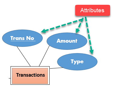
Attributes
It is a single-valued property of either an entity-type or a relationship-type.
For example, a lecture might have attributes: time, date, duration, place, etc.
An attribute in ER Diagram examples, is represented by an Ellipse
| Types of Attributes | Description |
|---|---|
| Simple attribute | Simple attributes can’t be divided any further. For example, a student’s contact number. It is also called an atomic value. |
| Composite attribute | It is possible to break down composite attribute. For example, a student’s full name may be further divided into first name, second name, and last name. |
| Derived attribute | This type of attribute does not include in the physical database. However, their values are derived from other attributes present in the database. For example, age should not be stored directly. Instead, it should be derived from the DOB of that employee. |
| Multivalued attribute | Multivalued attributes can have more than one values. For example, a student can have more than one mobile number, email address, etc. |